W-Band series-fed patch array architecture used for the 76–81 GHz design and simulation study.
Executive summary
- Band: 76–81 GHz
- Goal: stable beam + manufacturable feed architecture
- Method: full-wave FEM simulation + optimization
- Outcome: consistent radiation behavior across band
Key results (simulated)
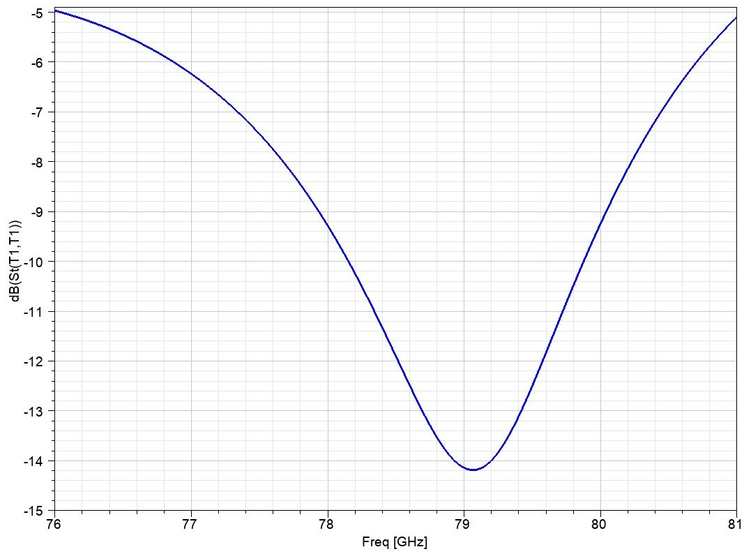
- S11 (band): better than −5 dB across 76–81 GHz
- S11 (best point): below −10 dB near 79 GHz
- Peak gain: ~11 dBi
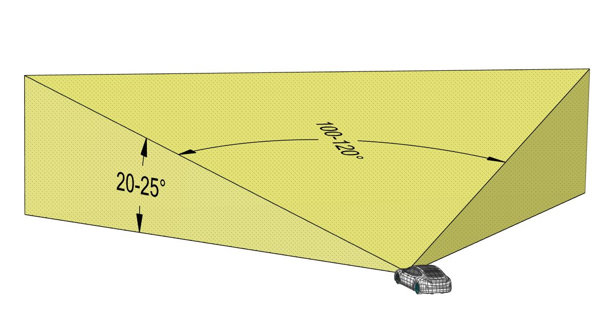
- Beamwidth (6 dB): ~100° azimuth, ~50° elevation
Overview
Tetra Elements developed and simulated an advanced W-Band (76–81 GHz) series-fed patch antenna array intended for automotive, industrial, and aerial radar systems. The design emphasizes beam consistency, practical PCB implementation, and impedance stability across the operating band.
Why this matters: In mmWave radar, stable beam behavior and predictable matching are essential for reliable detection performance and system integration—especially when packaging and real-world constraints are involved.
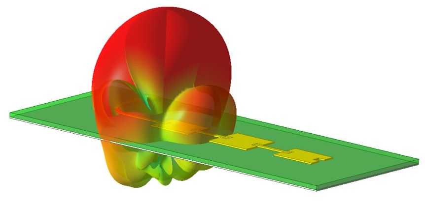
3D antenna model with overlaid radiation pattern visualization.
Design highlights
The antenna uses a hybrid feed approach that combines multi-section impedance transformation with inset feeding to support smooth impedance transitions and controlled excitation across the array. The design was tuned using full-wave FEM simulation to balance matching, phase behavior, and radiation symmetry.
What was optimized
- Patch geometry and spacing for radiation consistency
- Feed geometry for impedance transition and reflection control
- Feed position (inset) to tune input match and phase balance
- Array behavior across 76–81 GHz (beam stability)
What was prioritized
- Low-reflection behavior across the band
- Clean, symmetric beam shape
- Compact form factor suitable for PCB integration
- Manufacturing-ready architecture (repeatable layout)
Impedance matching results
Simulation results indicate stable input behavior across the W-Band operating range. The design achieves S11 better than −5 dB over 76–81 GHz, and improves to below −10 dB near 79 GHz.

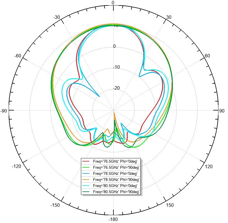
Radiation performance
The antenna demonstrates stable radiation characteristics across frequency, supporting predictable radar imaging and detection behavior. The reported simulated performance includes a peak gain of ~11 dBi, with approximately 100° azimuth and 50° elevation beamwidths (6 dB).
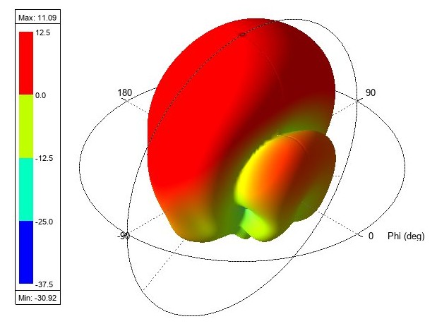
3D radiation pattern (simulation).

Key advantages
- Wide angular coverage for broader field of view
- Stable impedance behavior with reduced reflection across the band
- Compact PCB-based layout for low-profile integration
- Manufacturing-ready architecture optimized for repeatability
- Scalable platform adaptable to alternate bands and beam targets
Application areas
- Automotive radar (short- and mid-range sensing)
- Industrial sensing (distance, motion, and presence detection)
- UAV and drone radar systems requiring lightweight mmWave arrays
- Smart infrastructure and traffic monitoring
- Precision mapping and imaging radar
This antenna platform is designed to be tunable for alternative frequency bands, beamwidth targets, or bandwidth priorities—supporting both narrowband and broadband radar system needs.
Product insight
This W-Band array is one of Tetra Elements’ flagship mmWave antenna designs. It showcases our capability in high-frequency electromagnetic simulation, array feed engineering, beam shaping, and integration-oriented design. The platform can be adapted for custom requirements while maintaining a practical path to fabrication.
This design is available for purchase.
For licensing, customization, or integration support, contact us at info@tetraelements.com .
Note: Results shown are from full-wave simulation and optimization of the presented design configuration. Final performance in hardware can vary with fabrication tolerances, materials, connectors, packaging, and test setup.