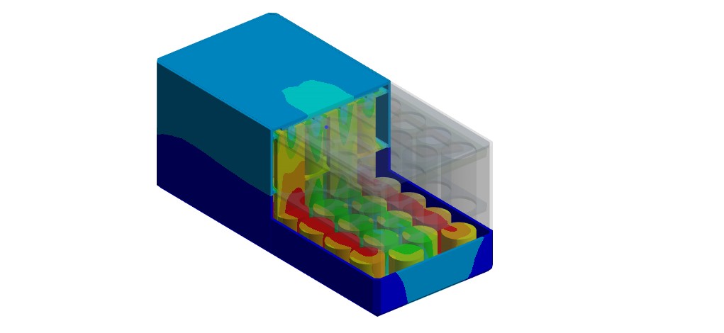
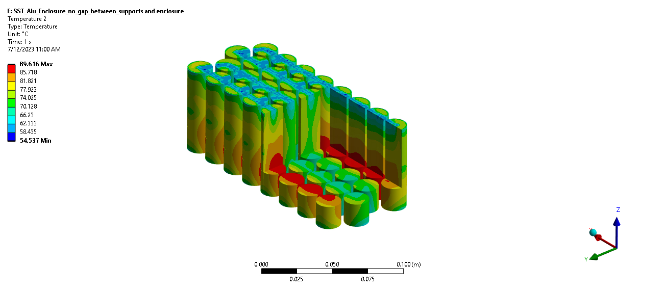
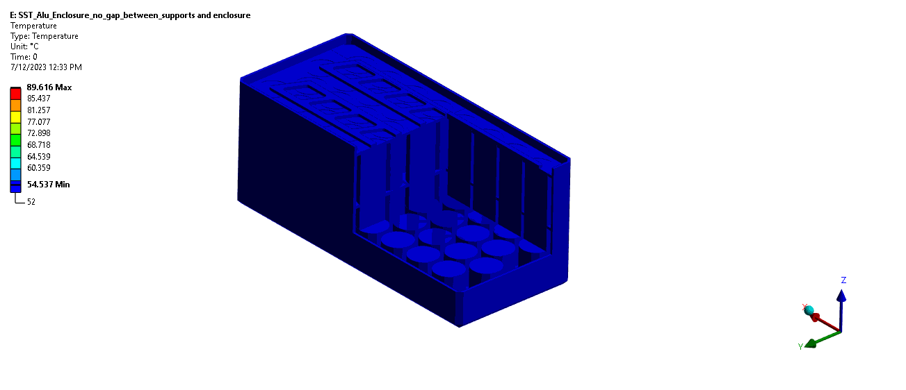
Battery pack thermal model visualization used for temperature distribution and cooling concept studies.
Executive summary
- System: Li-ion battery pack for electric scooter platform
- Objective: reduce hot spots and maintain safe operating temperature range
- Outputs: temperature distribution + cooling concept comparison
- Use: design guidance for enclosure, materials, and cooling path choices
What was evaluated
- Air cooling: enclosure airflow impact on pack temperature
- Cold plate concept: conduction-driven heat removal pathway
- Thermal risk drivers: heat generation, local hot spots, resistance paths
- Integration: practical paths to improve performance with packaging constraints
Overview
Battery pack design is inherently multidisciplinary: it must satisfy electrical performance, mechanical packaging, and thermal safety. The thermal aspect is especially critical for Li-ion cells, which operate reliably only within a limited temperature window. Exceeding that window increases degradation risk and can elevate the probability of thermal runaway under fault conditions.
Why this matters: Even when the average pack temperature is acceptable, localized hot spots can drive accelerated aging, reduced capacity retention, and inconsistent performance. Thermal analysis helps identify those hot spots early and guides cooling architecture decisions.
Simulation results
The figures below show representative temperature distributions for the battery pack under air-cooled operation and during cooling visualization. These plots support identifying the dominant thermal gradients and verifying whether the cooling path sufficiently reduces peak temperatures.
Cooling concepts
In addition to enclosure airflow, a conduction-based approach was also evaluated using a cold plate located at the bottom of the pack. This concept focuses on providing a low-thermal-resistance pathway out of the cells and into a controlled heat sink surface.
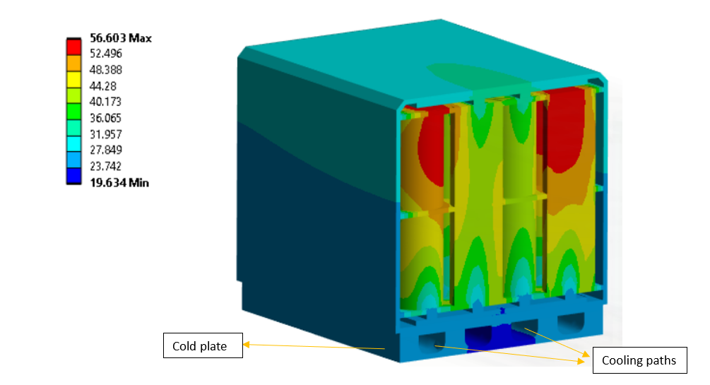
Battery pack cooling path concept using a cold plate at the bottom (conduction-driven heat removal).
Air cooling (enclosure)
- Leverages enclosure flow paths and available vents
- Performance depends strongly on flow uniformity and pressure drop
- Can be limited by local recirculation and stagnant regions
Cold plate (bottom)
- Targets hot spots through a direct conduction path
- Performance depends on contact resistance (pads, interfaces, flatness)
- Often offers more predictable thermal control in compact volumes
Engineering insights
The project outcomes translate into practical design actions that improve safety margin and temperature uniformity—especially when balancing packaging constraints and manufacturing realities.
- Electrical sizing of the battery pack: evaluate series/parallel cell counts to meet power and capacity targets.
- Thermal analysis of the pack: determine heat generation rates and temperature distribution within cells and across the pack.
- Cooling solution proposal: compare candidate solutions (air-cooled enclosure vs cold plate) based on performance and constraints.
- Cooling solution optimization: fine-tune the selected approach to reduce peak temperature and manage runaway risk.
- Material selection: assess materials for busbars, thermal pads, enclosure, and cell supports to lower thermal resistance and mitigate risk.
Recommendations and next steps
Model refinement
- Power profiles: simulate realistic drive cycles (peak load, sustained load, charging events).
- Interfaces: include contact resistance sensitivity (pads, adhesives, mechanical compression).
- Tolerance checks: evaluate worst-case scenarios (blocked vents, reduced fan flow, ambient rise).
Hardware validation
- Prototype testing: validate temperature predictions using thermocouples/IR imaging.
- Correlation: tune model parameters to match measured behavior and lock down design margin.
- Design iteration: adjust cooling path and material stack based on correlated results.
Need battery thermal management support?
We help teams evaluate cooling architectures and optimize battery pack thermal performance with simulation-backed design guidance. Contact us at info@tetraelements.com .
Note: Results shown are from simulation of the presented configurations. Final hardware performance can vary due to manufacturing tolerances, contact/interface quality, ambient conditions, and airflow variability in the final product enclosure.