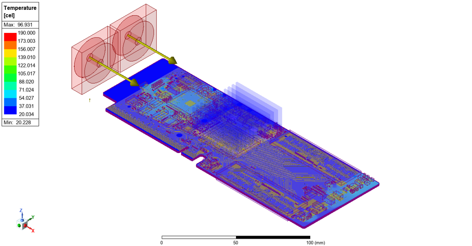
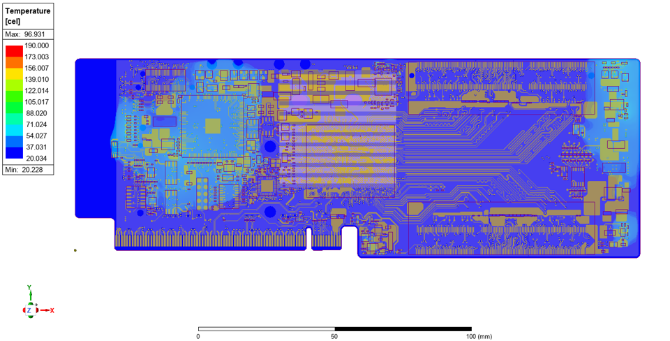
3D temperature distribution with optimized cooling (fans + heatsink) in Icepak.
Executive summary
- Workflow: SIwave electrical loss → Icepak thermal CFD
- Electrical outputs: DC IR drop, current density, power loss maps
- Thermal outputs: temperature distribution + airflow velocity field
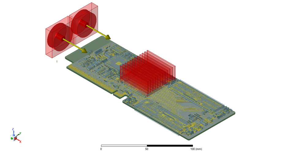
- Optimization: heatsink design + dual-fan airflow configuration
Why it matters
- Power loss becomes heat—hot spots can degrade reliability and lifetime
- IR drop impacts margins in high-current rails and dense PDNs
- Cooling must be engineered for compact systems with limited airflow
- Pre-fabrication insight reduces respins and derisks integration
Overview
Modern PCBs often host multiple high-current components and dense power-delivery networks (PDNs). In these systems, resistive losses in copper planes and interconnects can produce significant heat, and temperature rise can feed back into electrical performance and long-term reliability. This project uses a coupled approach to identify electrical loss mechanisms and translate them into a thermal model for cooling design and optimization.
Core idea: Use electrical simulation to quantify where power is dissipated, then use thermal CFD to engineer how that heat is removed.
Electro-thermal analysis workflow
The workflow begins in ANSYS SIwave to evaluate the PDN under DC conditions (IR drop and power loss). The resulting power dissipation distribution is then imported into ANSYS Icepak to model heat transfer and airflow, enabling direct comparison of passive and active cooling strategies.
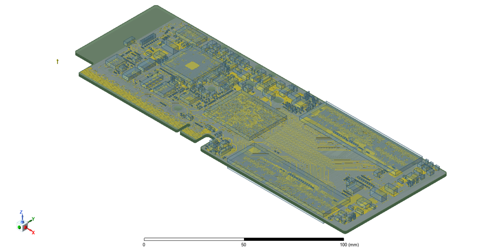
3D PCB model imported into Icepak for electro-thermal simulation and cooling design evaluation.
Electrical analysis in SIwave
The PDN is examined for DC behavior and loss mechanisms. The goal is to identify regions of elevated resistance-driven loss, concentrated current flow, and voltage margin reduction across high-current paths.
- Voltage-drop map (DC IR drop): identifies rails and regions with significant DC loss.
- Current-density map: highlights congested conduction paths and potential reliability concerns.
- Power-density map: converts electrical loss into heat sources for thermal simulation.
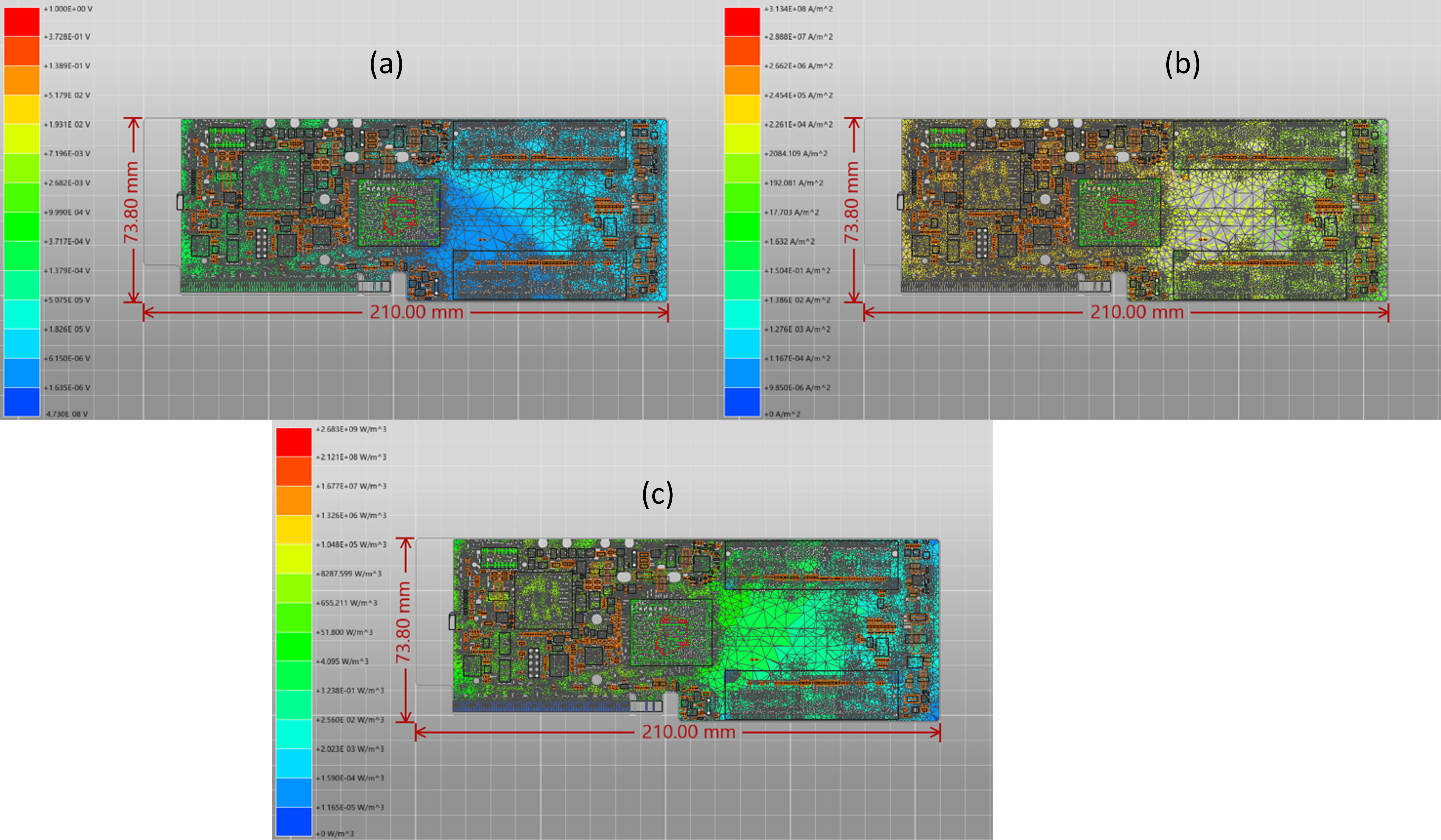
(a) Voltage-drop map (b) Current-density map (c) Power-density map (exported for Icepak).
Thermal profiling in Icepak
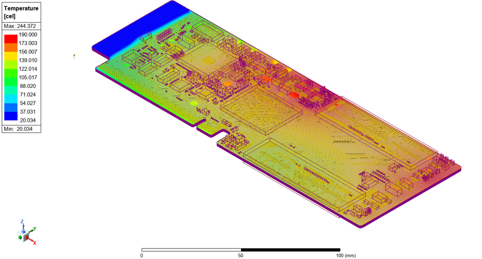
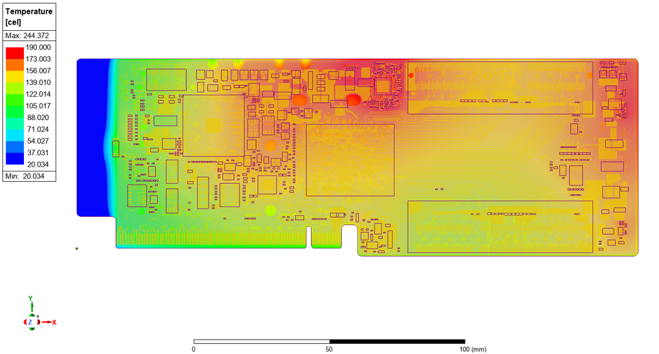
The imported loss distribution is used as the thermal excitation in Icepak. A baseline simulation is first run using natural convection (no fans / no heatsinks) to quantify worst-case hot spots and establish a reference. This baseline result informs cooling architecture selection and placement.
Baseline case
- Natural convection only
- Identifies dominant hot spots
- Quantifies whether passive cooling is sufficient
Optimized case
- Heatsink + dual-fan airflow
- Improves conduction paths and forced convection
- Targets peak reduction and uniformity
Cooling optimization results
A heatsink assembly and dual-fan configuration were introduced to create directional airflow and improve heat removal. The optimized configuration reduces peak temperatures and improves thermal uniformity across the board.
Result highlight: Peak temperature is reduced from ~244 °C to ~96 °C, while maintaining a stable low-temperature baseline near ambient in non-critical regions.
- Peak temperature: ~244 °C → ~96 °C (≈ 60% reduction)
- Minimum temperature: ~20 °C (stable baseline)
- Flow behavior: strong localized velocity near fan outlets, supporting effective convection
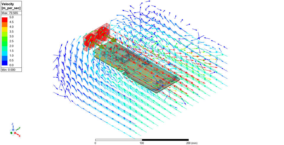
Air-velocity field illustrating optimized airflow distribution across the PCB.
Key capabilities demonstrated
- End-to-end electro-thermal co-simulation workflow (SIwave + Icepak)
- DC power integrity analysis: IR drop, current density, and loss mapping
- Thermal CFD evaluation of passive vs. active cooling strategies
- Parametric evaluation of heatsink geometry, fan placement, and airflow paths
- Design recommendations: trace/via strategy, copper distribution, and airflow control
- Reliability-focused insight using temperature and loss drivers
Application areas
This workflow applies directly to engineering teams developing compact systems where power delivery and cooling are tightly coupled:
- High-power electronics (converter and power-stage boards)
- RF front-end and communication PCBs with tight thermal margins
- Automotive and aerospace control modules requiring robust reliability
- Embedded systems with limited airflow and enclosure constraints
Project insight
This project highlights Tetra Elements’ capability to connect electrical loss mechanisms to thermal behavior and translate results into practical cooling recommendations. By combining electromagnetic/electrical analysis with CFD-based thermal modeling, we help teams optimize PCB designs for efficiency, reliability, and manufacturability—from power delivery to complete system cooling.
Need electro-thermal simulation support for your PCB?
For co-simulation setup, design optimization, or thermal reliability assessment, contact us at info@tetraelements.com .
Note: Results shown are simulation-based and can vary with component power profiles, material properties, enclosure leakage, fan curves, heatsink interface resistance, and manufacturing tolerances. Final sign-off should include lab validation when available.