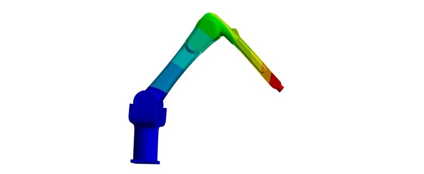
Total deformation contour under lifting load (FEA result).
Executive summary
- Goal: assess stress, deformation, and lifting capacity
- Focus: joint regions + geometric transitions
- Outputs: stress hotspots, displacement limits, capacity estimate
- Use: design iteration + safety margin planning
Key result (reported)
- Vertical load capacity: ~1100 lbf (reported case)
- Hotspot locations: near joints / high-curvature features
- Design outcome: actionable insights for reinforcement and stiffness control
Overview
Robot arms are mission-critical structures in automation systems used for material handling, assembly, and precision operations. A structural FEA workflow helps quantify how loads translate into stress and deflection, which directly affects safety, repeatability, and positional accuracy. This study evaluates stress distribution, deformation, and an estimated lifting load capacity for a representative arm configuration.
Why this matters: In robot arms, performance limitations are often driven by joint-adjacent stress concentrations and stiffness-driven deflection. Identifying these early enables targeted reinforcement without excessive mass.
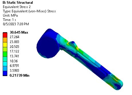
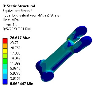
Stress results
Stress contours highlight how load paths flow through the arm and where local geometry drives amplification. Peak stresses typically occur near joints, mount interfaces, and sharp transitions, where bending moments and constraint reactions are highest.
Vertical load capacity
A vertical lifting scenario was evaluated to estimate the maximum allowable payload before exceeding the selected stress limit (e.g., yield-based or allowable-based criterion). For the reported configuration and assumptions, the vertical capacity is approximately 1100 lbf.
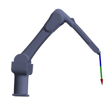
Vertical load capacity result: ~1100 lbf (reported case).
Engineering insights
- Multiple scenarios: loads can be assessed from nominal operation through maximum anticipated cases to map margins.
- Hotspot identification: joint-adjacent regions and geometric complexity drive stress concentration and govern allowable load.
- Deformation control: limiting deflection is essential for accuracy; stiffness improvements can outperform pure strength upgrades.
- Capacity definition: load capacity should be tied to a clear criterion (yield/allowable, deflection limit, fatigue, or combined).
Recommendations
Structural improvements
- Add local fillets / smooth transitions at high-stress corners.
- Reinforce joint-adjacent regions with ribs or local thickening.
- Evaluate bolt patterns / mount stiffness for reaction-load reduction.
Next-step validation
- Run sensitivity studies on payload position and moment arm.
- Include material allowables and realistic boundary stiffness.
- Add fatigue assessment if the arm sees repeated cycles.
Need robot structural verification or design optimization?
We support stress/deformation, stiffness optimization, joint modeling, and fatigue workflows for robotics structures. Contact us at info@tetraelements.com .
Note: Results shown are simulation-based and depend on the assumed materials, constraints, load locations, and acceptance criteria. Final capacity should be confirmed with validated inputs and, when required, physical testing.