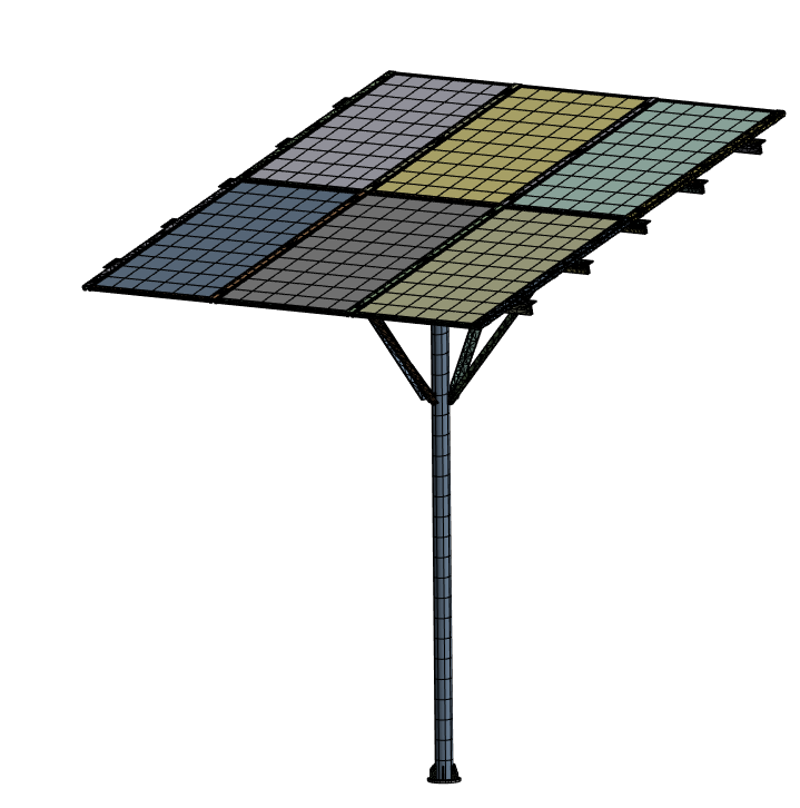
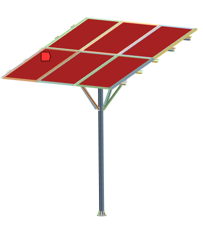
Meshed structural model used for the solar panel support analysis.
Executive summary
- Loads: static, dynamic (wind/vibration), thermal
- Analyses: modal, stress/deformation, thermal effects
- Focus: vibration-prone regions + stress concentrations
- Outcome: actionable reinforcement and mitigation recommendations
Key takeaways
- Modal drivers: low-frequency modes identified (field-relevant)
- Structural hotspots: joint and frame regions highlighted
- Thermal effects: deformation/stress sensitivity noted
- Next steps: add damping, reinforcement, and thermal allowances
Overview
The solar panel structure is exposed to environmental loading and temperature variation that can drive fatigue, loosening at joints, and long-term deformation. The goal of this study was to evaluate the structure under representative static, dynamic, and thermal conditions, and to identify design improvements that increase stability and service life.
Why this matters: The lowest structural modes often sit in the same range as wind-induced excitation. Identifying resonance-prone regions early helps prevent amplified vibration, connection wear, and premature damage.
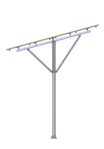
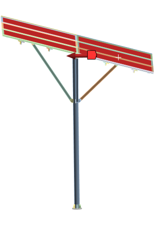
Structure overview

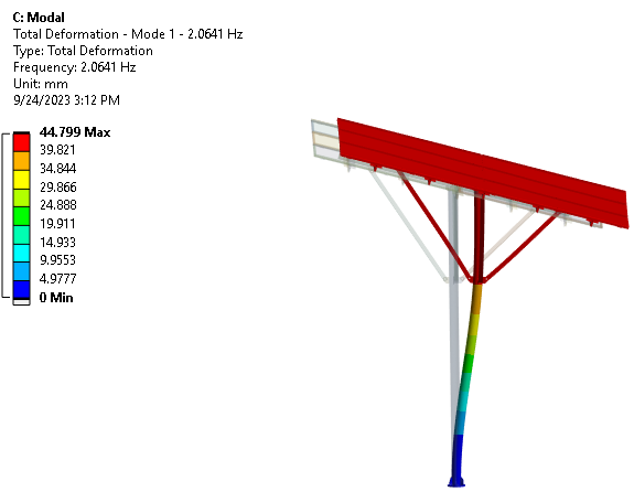
Modal analysis
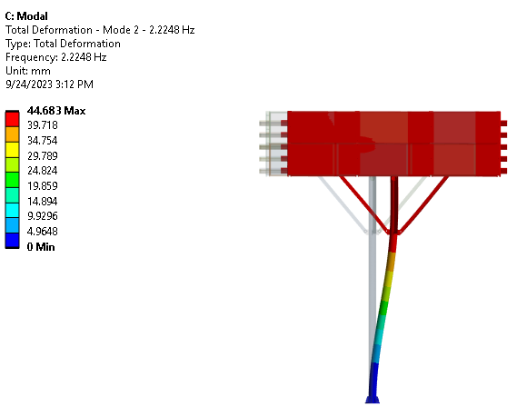
Modal analysis was used to determine the structure’s natural frequencies and mode shapes. These modes highlight where the structure is most likely to experience vibration amplification when excited by wind, machinery coupling, or installation-induced vibration.
Insights
- Fundamental modes identified in the low-frequency range.
- Mode shapes reveal vibration-sensitive members and joints.
- Results guide targeted stiffening and damping placement.
Recommendations
- Add local stiffness in high-participation regions.
- Introduce damping/isolation at mounting interfaces when feasible.
- Verify that expected operating excitation avoids dominant modes.
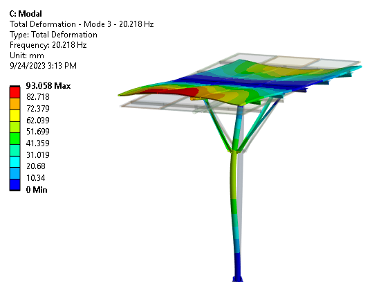
Mode 3 shape (fr = 20.218 Hz).
Static and dynamic loading analysis
Static and dynamic loading checks were used to evaluate stress distribution, deformation, and the sensitivity of the structure to severe conditions. These results highlight whether reinforcements are needed to improve stiffness, reduce local stress concentration, and protect connections.
Insights
- Static load capacity concerns can concentrate at joints and corners.
- Dynamic response may elevate stress in members aligned with modal shapes.
- Deformation trends help validate stiffness targets and alignment needs.
Recommendations
- Add reinforcements (ribs/braces) in high-stress regions.
- Smooth transitions and reduce sharp discontinuities at connections.
- Check fastener/connection integrity under combined loading.
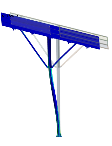
Deformation contour (static response view).
Thermal loading analysis
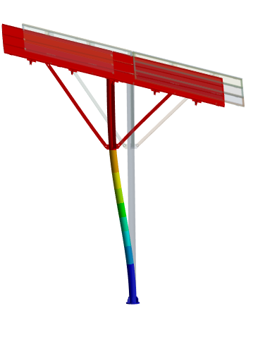
Thermal loading can introduce expansion-driven deformation and stress, especially at interfaces where materials, thicknesses, or constraints change. The thermal study highlights where allowances, insulation, or joint design improvements can reduce thermally induced issues.
Insights
- Thermal expansion can drive measurable deformation and misalignment risk.
- Stress concentration often occurs near constraints and material junctions.
- Daily cycling can contribute to loosening and fatigue at connections.
Recommendations
- Use thermal isolation/insulation where appropriate.
- Introduce expansion allowances (slots/compliance) at mounts.
- Select materials/joints to reduce CTE mismatch sensitivity.
High-temperature load application (thermal boundary condition view).
Buckling check
A buckling assessment helps quantify stability margins under compressive or extreme load cases. The goal is to identify buckling-sensitive members and guide bracing or stiffening strategies before deployment.
Recommendation: For outdoor structures, buckling margins should consider load combinations and field uncertainties (gust factors, installation variability, and connection slip).
Recommendations
The simulation results provide design-direction guidance for improving stability under vibration, static loading, and thermal cycling. Key recommendations include:
- Material selection and thermal mitigation: consider insulation, thermal breaks, and joint allowances to reduce thermal stress and deformation.
- Vibration damping: apply damping strategies at resonance-prone regions identified by mode shapes.
- Structural reinforcement: add bracing/ribs in high-stress members to improve dynamic robustness (wind/severe conditions).
- Buckling prevention: strengthen compressive members and add bracing where stability margins are limited.
Note: Final design sign-off should include load cases specific to the installation site (wind code, mounting conditions, and thermal envelope) and validated material/connection properties.
Need a structural validation plan for an outdoor support system?
We can help you build a simulation workflow for site-specific loads, modal separation, and reliability-focused design changes. Contact us at info@tetraelements.com .