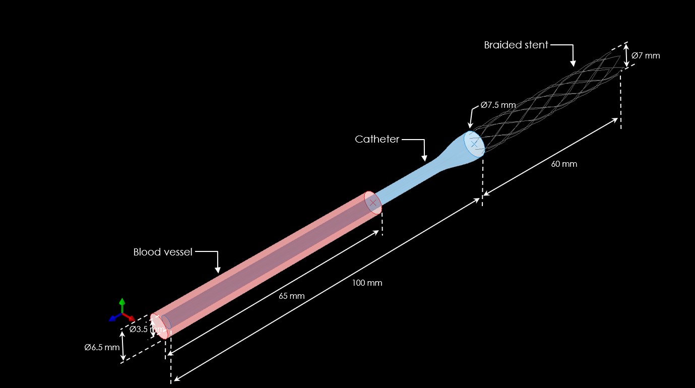
Baseline braided stent geometry and dimensions used for the structural analysis.
Executive summary
- Device: braided stent (nitinol-class alloy assumed)
- Goal: evaluate stress, deformation, and contact behavior
- Analyses: deployment mechanics + stress contours + contact forces
- Outcome: identifies hotspots and interaction loads for design refinement
What the results support
- Safety: avoid stress peaks that can trigger fatigue/fracture
- Performance: preserve flexibility and conformability
- Deployment: reduce force spikes during expansion/placement
- Interaction: manage contact pressure/shear at interfaces
Overview
A braided stent is a flexible tubular scaffold used to restore or maintain vessel patency. Many braided stents are based on superelastic nitinol (nickel–titanium) or similar alloys, allowing large recoverable deformation during delivery and deployment. The braided architecture supports: radial expansion under pressure while maintaining conformability to vessel geometry.
Why this matters: Stents must balance competing requirements—radial strength, flexibility, fatigue life, and controlled vessel interaction. Simulation helps identify where stress and contact loads concentrate before prototyping.
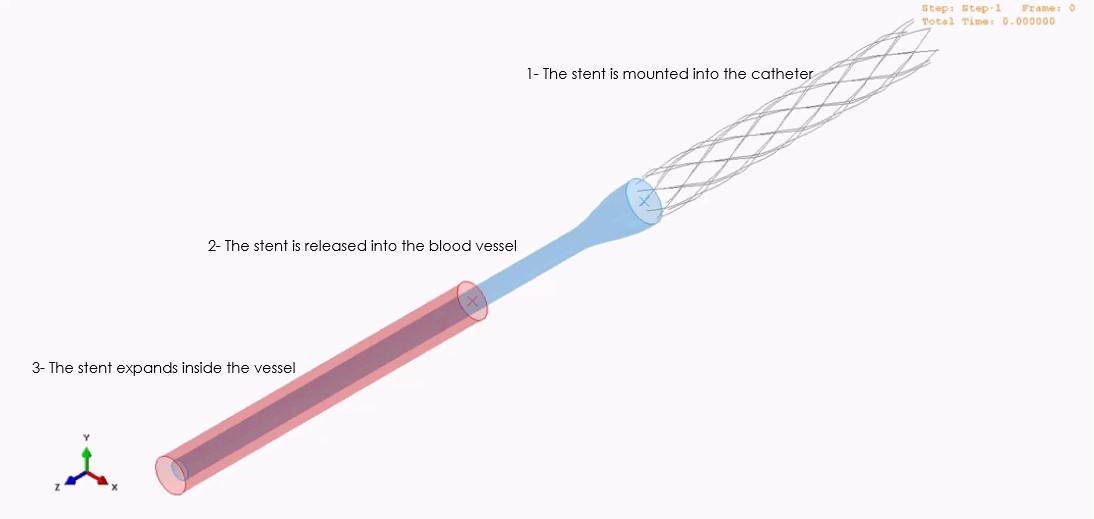
Stenting mechanism
Implantation typically uses a catheter-based delivery system, where the stent is constrained during delivery and then allowed to expand at the target location. The braided structure can change length as it expands—an important behavior that influences deployment accuracy and wall interaction.
Deployment response visualization (simulation view).
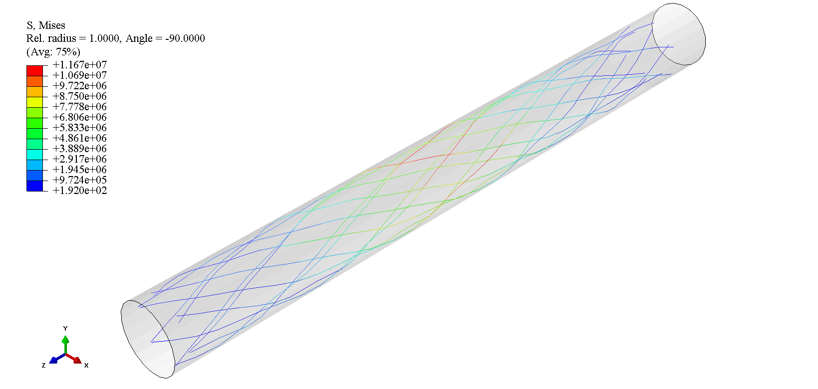
Stress and deformation
The stress contours help identify structural hotspots that may govern fatigue life or localized failure risk. In braided stents, peak stresses often occur at wire crossovers, bending zones, and constrained contact regions.
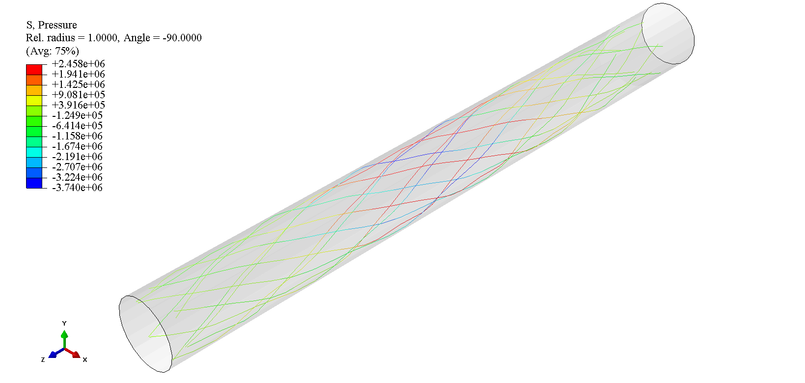
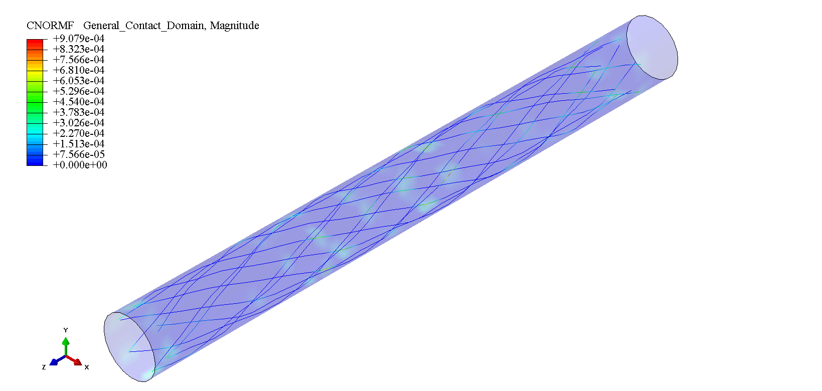
Contact forces
Contact mechanics results provide insight into how the stent interacts with surrounding surfaces during deployment. Normal contact relates to compressive interface loading, while shear contact relates to tangential forces that can influence migration risk and local tissue interaction in more detailed vessel models.

Simulation workflow
The simulation process focuses on capturing deployment mechanics, stress evolution, and contact behavior under representative constraints. The objective is to translate complex mechanical interaction into actionable design changes (geometry, braid pattern, material model, and deployment strategy).
Stent FEA simulation process overview.
Engineering insights
Finite Element Analysis (FEA) enables fast iteration on stent architectures by revealing stress hotspots, deployment sensitivities, and interface loading trends before costly prototyping. Typical design insights enabled by FEA include:
Design and safety
- Stress concentration control: identify and reduce peak stress regions that drive fatigue.
- Geometry tuning: refine wire diameter, braid angle, and crossover density for balanced response.
- Flexibility vs. strength: evaluate radial support while preserving conformability.
- Fatigue readiness: locate cyclic bending hotspots for durability-focused iteration.
Deployment and interaction
- Deployment simulation: evaluate how constraints affect expansion and shortening behavior.
- Contact pressure study: map interface loads that can inform vessel interaction modeling.
- Balloon/stent compatibility: evaluate interaction effects during expansion (when applicable).
- Procedure robustness: reduce force spikes that can complicate deployment.
Need simulation support for a medical device mechanism?
We can help build a repeatable workflow for nonlinear contact, deployment mechanics, and durability-focused iteration. Contact us at info@tetraelements.com .