
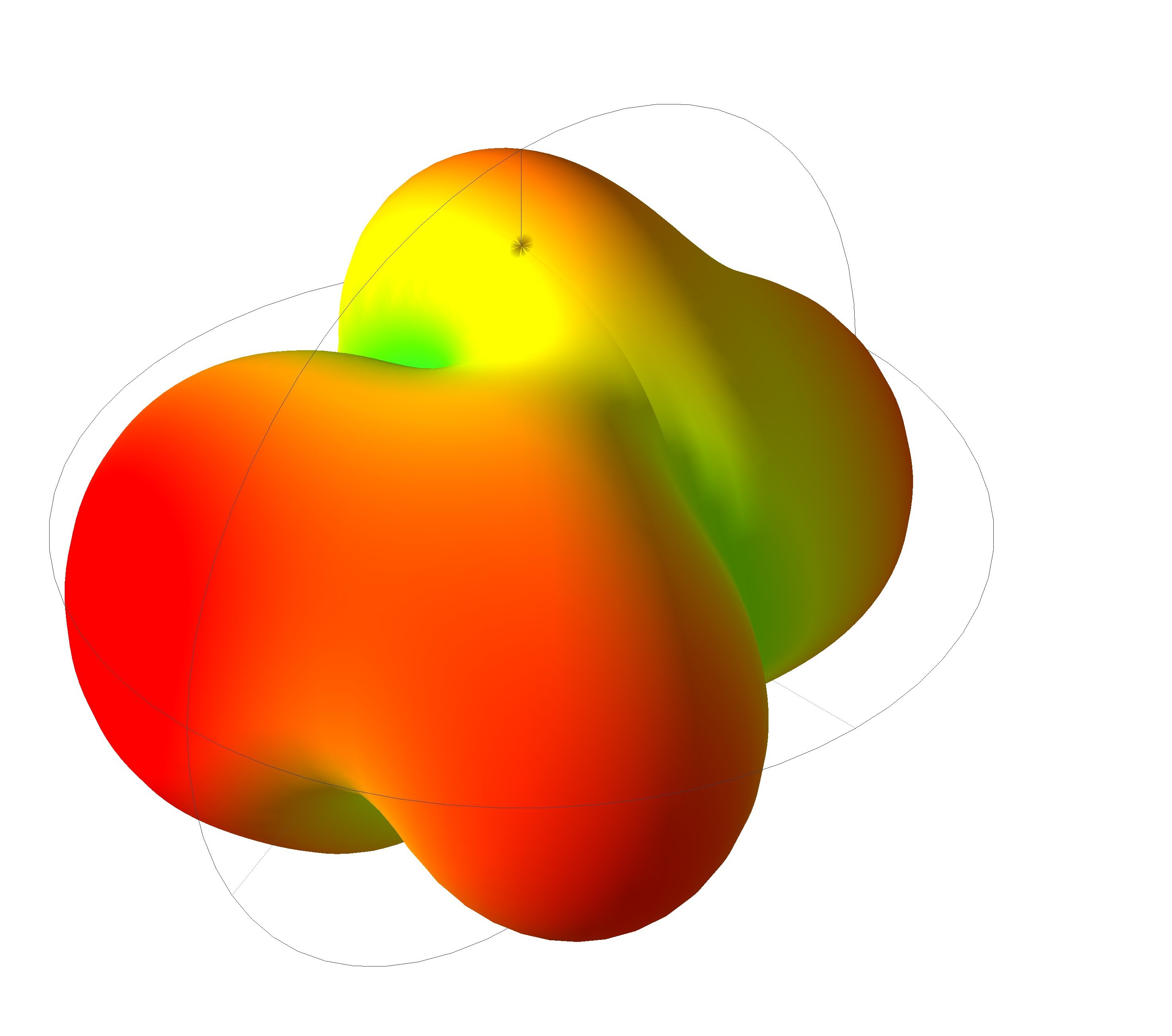
Far-field visualization for the PIFA packaged inside the Wi-Fi router enclosure (simulation).
Executive summary
- Antenna type: Planar Inverted-F Antenna (PIFA)
- Use case: compact Wi-Fi router antenna system
- Method: full-wave EM simulation + packaging evaluation
- Focus: S11, impedance stability, radiation shape under enclosure effects
Key results (simulated)
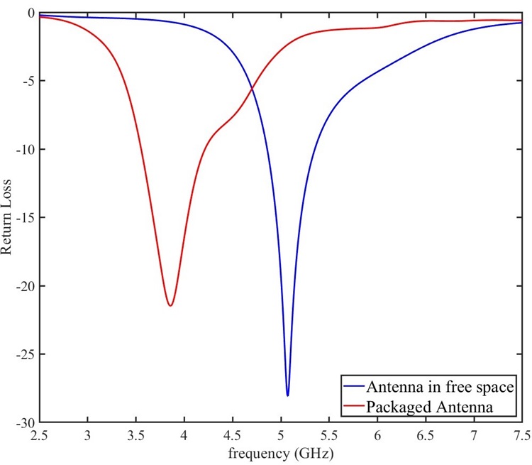
- Free-space resonance: ~5 GHz (S11 ≈ −28 dB)
- Packaged resonance: ~3.85 GHz (S11 ≈ −22 dB)
- Peak gain (free space): ~3.5 dBi
- Peak gain (packaged): ~2 dBi
- Total efficiency: >99% (reported)
Overview
Microstrip antenna systems are widely used in compact wireless products because they enable low-profile integration, repeatable PCB fabrication, and practical tuning using full-wave simulation. In this work, Tetra Elements designed and evaluated a PIFA intended for a Wi-Fi router platform.
Why this matters: Antennas that look well-matched in free space can shift substantially once placed inside an enclosure. Plastics, nearby conductors, cable routes, and ground structure can alter impedance, resonance, and radiation coverage—so packaging must be evaluated early.
Design overview
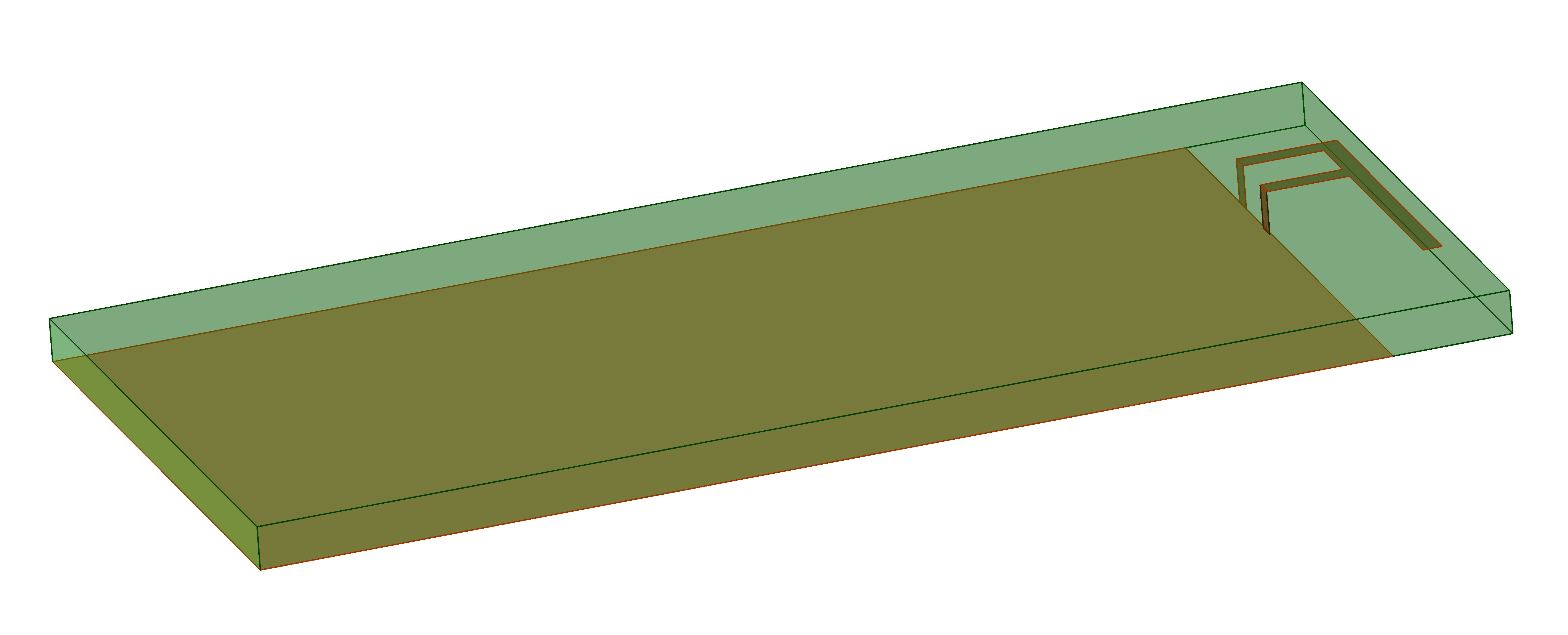
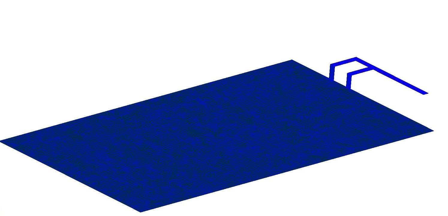
The antenna was designed and tuned to meet a compact integration target while maintaining stable matching and usable coverage. The baseline design intent and material stack were:
Target parameters
- Nominal resonant frequency: 5 GHz (free-space target)
- Substrate: Duroid (εr ≈ 2.2)
- Geometry: optimized dimensions based on simulation tuning
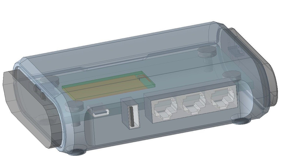
Integration considerations
- Enclosure material and thickness (e.g., ABS plastic)
- Router chassis / ground proximity and current return paths
- Near-field coupling to nearby components and structures
- Pattern distortion and coverage stability
Simulation setup
Two simulation scenarios were analyzed to isolate packaging effects:
- Free-space configuration: baseline antenna performance without enclosure influence.
- Packaged configuration: antenna placed inside the Wi-Fi router enclosure to capture detuning and pattern changes.

Return loss (S11)
The return loss results indicate strong matching in both cases, with a clear resonance shift introduced by packaging. In free space, the antenna reaches approximately −28 dB near 5 GHz. When packaged inside the router, the resonance shifts to approximately −22 dB near 3.85 GHz.
Interpretation: The enclosure environment changes the effective permittivity and near-field loading around the radiator, which shifts the input impedance trajectory and moves the resonant point. This is a common outcome in compact consumer devices and is exactly why “in-product” simulation is required for reliable tuning.
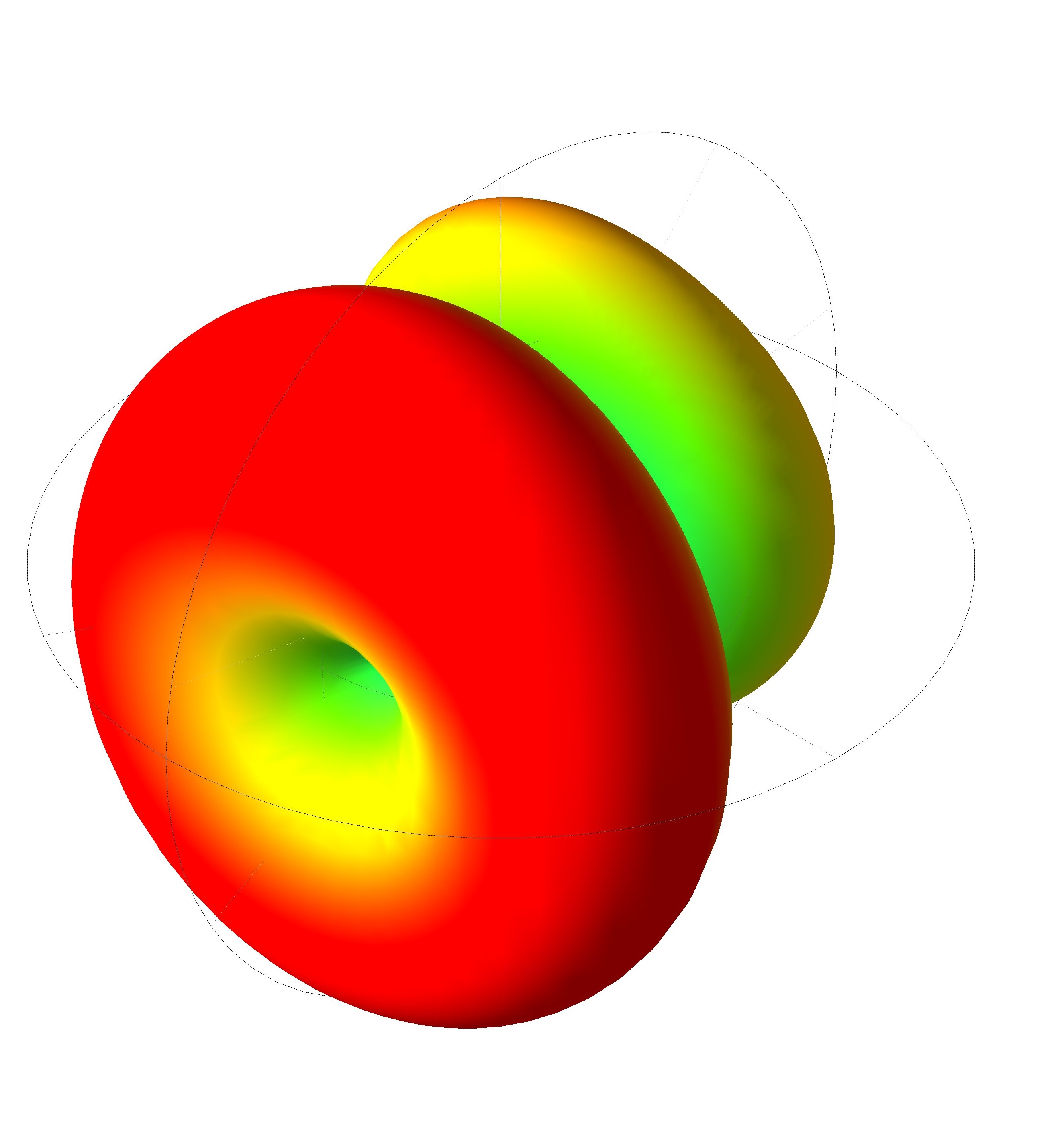
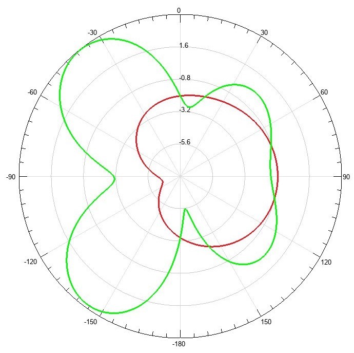
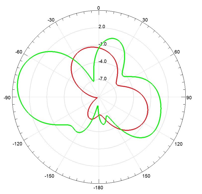
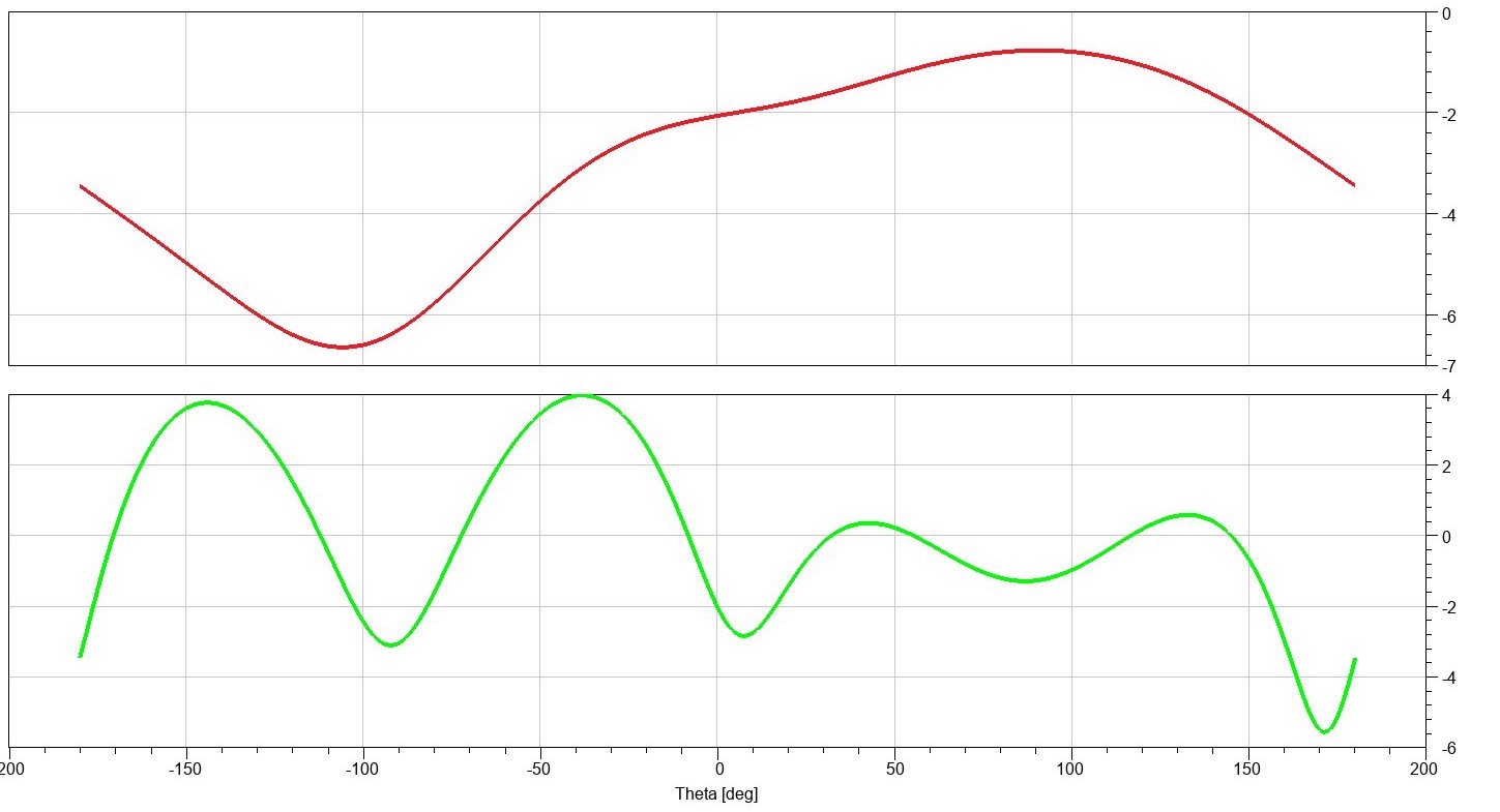
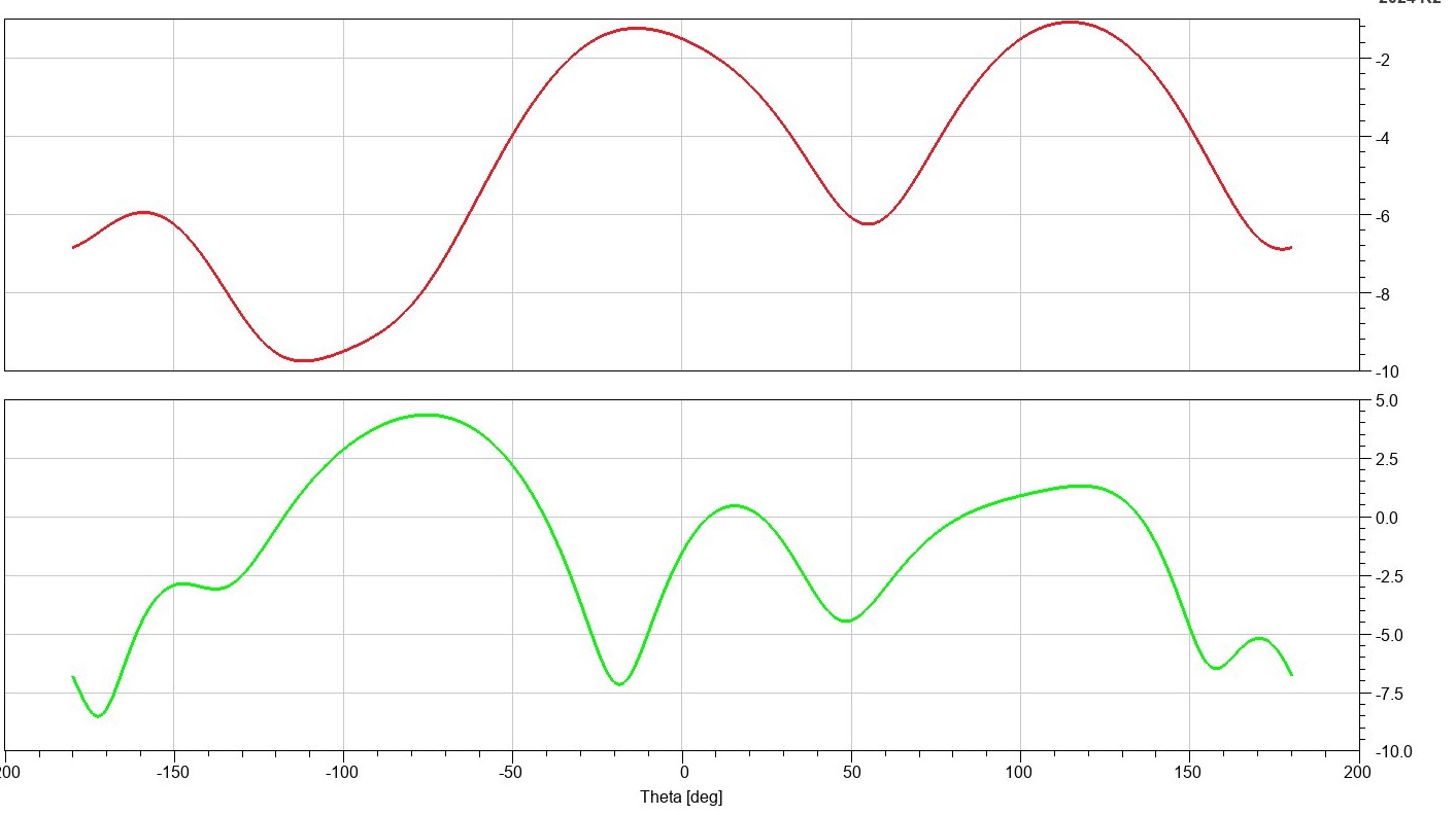
Radiation performance
Radiation results show that packaging not only shifts the resonant frequency but also changes the shape and uniformity of the radiation pattern. In free space, the antenna exhibits a relatively symmetric coverage pattern with a peak gain near ~3.5 dBi at 5 GHz. In the packaged case, the peak gain shifts to ~2 dBi near 3.85 GHz, with increased pattern irregularity due to enclosure interactions and nearby structures.
Gain & efficiency
The reported simulation results indicate high radiation efficiency in both configurations. The unpackaged antenna reaches approximately ~3.5 dBi gain with >99.8% total efficiency. The packaged antenna reaches approximately ~2 dBi while maintaining >99% total efficiency, demonstrating that the primary impact of packaging is detuning and pattern distortion rather than severe loss.
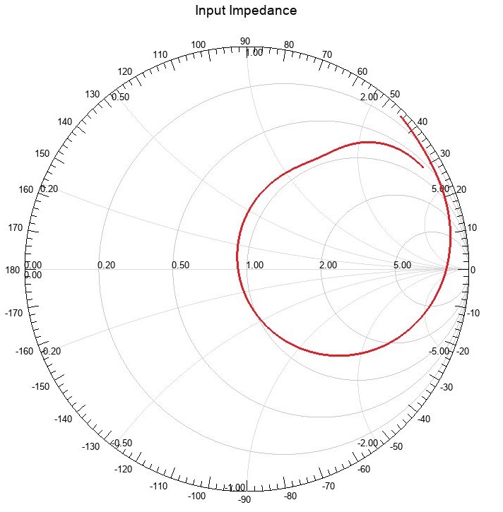
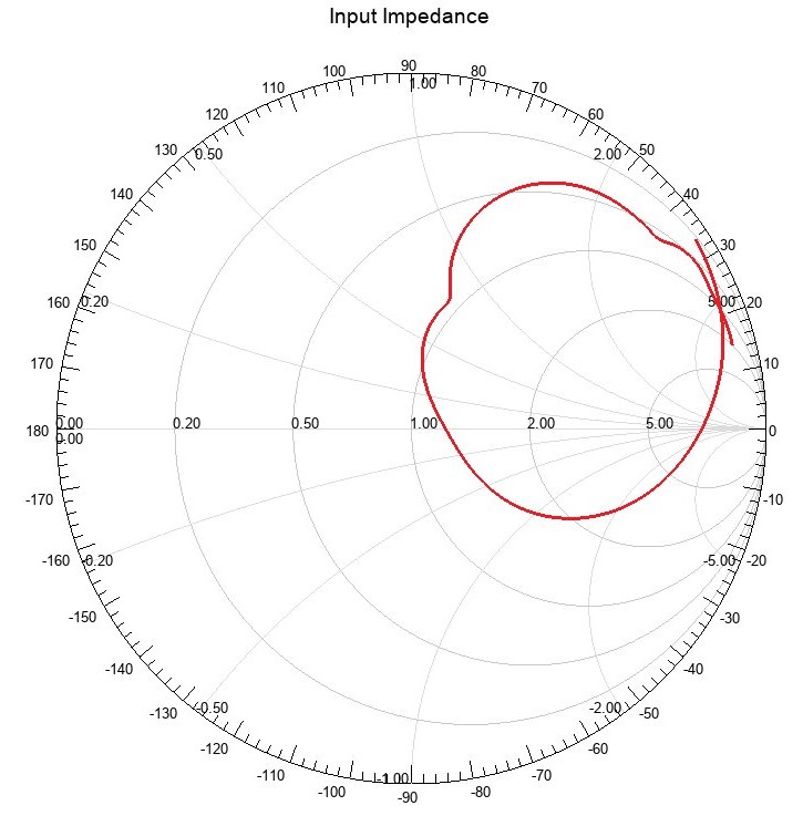
Input impedance
The input impedance plots provide a clear view of how the resonance shifts between configurations. In free space, the impedance trajectory approaches the center of the Smith chart near 5 GHz, indicating strong matching and efficient power transfer. In the packaged scenario, the impedance trajectory shifts and approaches the center near 3.85 GHz, demonstrating enclosure-driven detuning.
Recommendations and next steps
Design tuning
- Packaging-aware tuning: retune geometry/feed to recover the desired band in the final enclosure.
- Bandwidth robustness: optimize for margin against tolerance (plastic εr variation, assembly placement).
- Near-field checks: identify the dominant coupling paths and mitigate via clearance or shielding strategy.
Validation
- Prototype fabrication: build and test the antenna with the final enclosure and fixtures.
- Measurement correlation: compare S11 and pattern measurements vs simulation and close gaps.
- System integration: verify performance with nearby electronics, cables, and mechanical constraints.
Need a packaging-aware antenna design?
We help teams tune antennas inside real enclosures and validate performance with simulation-backed design guidance. Contact us at info@tetraelements.com .
Note: Results shown are from full-wave simulation of the presented design configurations. Final hardware performance can vary with fabrication tolerances, material property variation, connector/fixture influence, assembly placement, and measurement setup.